|
Reference documentation for deal.II version 9.1.0-pre
|
|
Reference documentation for deal.II version 9.1.0-pre
|
Functions | |
Creating meshes for basic geometries | |
| template<int dim, int spacedim> | |
| void | hyper_cube (Triangulation< dim, spacedim > &tria, const double left=0., const double right=1., const bool colorize=false) |
| template<int dim> | |
| void | simplex (Triangulation< dim, dim > &tria, const std::vector< Point< dim >> &vertices) |
| Triangulation of a d-simplex with (d+1) vertices and mesh cells. More... | |
| template<int dim, int spacedim> | |
| void | subdivided_hyper_cube (Triangulation< dim, spacedim > &tria, const unsigned int repetitions, const double left=0., const double right=1.) |
| template<int dim, int spacedim> | |
| void | hyper_rectangle (Triangulation< dim, spacedim > &tria, const Point< dim > &p1, const Point< dim > &p2, const bool colorize=false) |
| template<int dim, int spacedim> | |
| void | subdivided_hyper_rectangle (Triangulation< dim, spacedim > &tria, const std::vector< unsigned int > &repetitions, const Point< dim > &p1, const Point< dim > &p2, const bool colorize=false) |
| template<int dim> | |
| void | subdivided_hyper_rectangle (Triangulation< dim > &tria, const std::vector< std::vector< double >> &step_sizes, const Point< dim > &p_1, const Point< dim > &p_2, const bool colorize=false) |
| template<int dim> | |
| void | subdivided_hyper_rectangle (Triangulation< dim > &tria, const std::vector< std::vector< double >> &spacing, const Point< dim > &p, const Table< dim, types::material_id > &material_id, const bool colorize=false) |
| template<int dim, int spacedim> | |
| void | cheese (Triangulation< dim, spacedim > &tria, const std::vector< unsigned int > &holes) |
| Rectangular domain with rectangular pattern of holes. More... | |
| template<int dim> | |
| void | plate_with_a_hole (Triangulation< dim > &tria, const double inner_radius=0.4, const double outer_radius=1., const double pad_bottom=2., const double pad_top=2., const double pad_left=1., const double pad_right=1., const Point< dim > center=Point< dim >(), const types::manifold_id polar_manifold_id=0, const types::manifold_id tfi_manifold_id=1, const double L=1., const unsigned int n_slices=2, const bool colorize=false) |
| Rectangular plate with an (offset) cylindrical hole. More... | |
| template<int dim> | |
| void | general_cell (Triangulation< dim > &tria, const std::vector< Point< dim >> &vertices, const bool colorize=false) |
| template<int dim> | |
| void | parallelogram (Triangulation< dim > &tria, const Point< dim >(&corners)[dim], const bool colorize=false) |
| template<int dim> | |
| void | parallelepiped (Triangulation< dim > &tria, const Point< dim >(&corners)[dim], const bool colorize=false) |
| template<int dim> | |
| void | subdivided_parallelepiped (Triangulation< dim > &tria, const unsigned int n_subdivisions, const Point< dim >(&corners)[dim], const bool colorize=false) |
| template<int dim> | |
| void | subdivided_parallelepiped (Triangulation< dim > &tria, const unsigned int(&n_subdivisions)[dim], const Point< dim >(&corners)[dim], const bool colorize=false) |
| template<int dim, int spacedim> | |
| void | subdivided_parallelepiped (Triangulation< dim, spacedim > &tria, const Point< spacedim > &origin, const std::array< Tensor< 1, spacedim >, dim > &edges, const std::vector< unsigned int > &subdivisions=std::vector< unsigned int >(), const bool colorize=false) |
| template<int dim> | |
| void | enclosed_hyper_cube (Triangulation< dim > &tria, const double left=0., const double right=1., const double thickness=1., const bool colorize=false) |
| template<int dim> | |
| void | hyper_ball (Triangulation< dim > &tria, const Point< dim > ¢er=Point< dim >(), const double radius=1., const bool attach_spherical_manifold_on_boundary_cells=false) |
| template<int spacedim> | |
| void | hyper_sphere (Triangulation< spacedim-1, spacedim > &tria, const Point< spacedim > ¢er=Point< spacedim >(), const double radius=1.) |
| template<int dim> | |
| void | quarter_hyper_ball (Triangulation< dim > &tria, const Point< dim > ¢er=Point< dim >(), const double radius=1.) |
| template<int dim> | |
| void | half_hyper_ball (Triangulation< dim > &tria, const Point< dim > ¢er=Point< dim >(), const double radius=1.) |
| template<int dim> | |
| void | cylinder (Triangulation< dim > &tria, const double radius=1., const double half_length=1.) |
| template<int dim> | |
| void | truncated_cone (Triangulation< dim > &tria, const double radius_0=1.0, const double radius_1=0.5, const double half_length=1.0) |
| template<int dim, int spacedim> | |
| void | hyper_cross (Triangulation< dim, spacedim > &tria, const std::vector< unsigned int > &sizes, const bool colorize_cells=false) |
| A center cell with stacks of cell protruding from each surface. More... | |
| template<int dim> | |
| void | hyper_L (Triangulation< dim > &tria, const double left=-1., const double right=1., const bool colorize=false) |
| template<int dim> | |
| void | hyper_cube_slit (Triangulation< dim > &tria, const double left=0., const double right=1., const bool colorize=false) |
| template<int dim> | |
| void | hyper_shell (Triangulation< dim > &tria, const Point< dim > ¢er, const double inner_radius, const double outer_radius, const unsigned int n_cells=0, bool colorize=false) |
| template<int dim> | |
| void | half_hyper_shell (Triangulation< dim > &tria, const Point< dim > ¢er, const double inner_radius, const double outer_radius, const unsigned int n_cells=0, const bool colorize=false) |
| template<int dim> | |
| void | quarter_hyper_shell (Triangulation< dim > &tria, const Point< dim > ¢er, const double inner_radius, const double outer_radius, const unsigned int n_cells=0, const bool colorize=false) |
| template<int dim> | |
| void | cylinder_shell (Triangulation< dim > &tria, const double length, const double inner_radius, const double outer_radius, const unsigned int n_radial_cells=0, const unsigned int n_axial_cells=0) |
| template<int dim, int spacedim> | |
| void | torus (Triangulation< dim, spacedim > &tria, const double R, const double r) |
| template<int dim> | |
| void | hyper_cube_with_cylindrical_hole (Triangulation< dim > &triangulation, const double inner_radius=.25, const double outer_radius=.5, const double L=.5, const unsigned int repetitions=1, const bool colorize=false) |
| template<int dim> | |
| void | concentric_hyper_shells (Triangulation< dim > &triangulation, const Point< dim > ¢er, const double inner_radius=0.125, const double outer_radius=0.25, const unsigned int n_shells=1, const double skewness=0.1, const unsigned int n_cells_per_shell=0, const bool colorize=false) |
| void | moebius (Triangulation< 3, 3 > &tria, const unsigned int n_cells, const unsigned int n_rotations, const double R, const double r) |
Creating meshes from other meshes | |
| template<int dim, int spacedim> | |
| void | merge_triangulations (const Triangulation< dim, spacedim > &triangulation_1, const Triangulation< dim, spacedim > &triangulation_2, Triangulation< dim, spacedim > &result, const double duplicated_vertex_tolerance=1.0e-12, const bool copy_manifold_ids=false) |
| template<int dim, int spacedim> | |
| void | merge_triangulations (const std::initializer_list< const Triangulation< dim, spacedim > *const > triangulations, Triangulation< dim, spacedim > &result, const double duplicated_vertex_tolerance=1.0e-12, const bool copy_manifold_ids=false) |
| template<int dim, int spacedim> | |
| void | create_union_triangulation (const Triangulation< dim, spacedim > &triangulation_1, const Triangulation< dim, spacedim > &triangulation_2, Triangulation< dim, spacedim > &result) |
| template<int dim, int spacedim> | |
| void | create_triangulation_with_removed_cells (const Triangulation< dim, spacedim > &input_triangulation, const std::set< typename Triangulation< dim, spacedim >::active_cell_iterator > &cells_to_remove, Triangulation< dim, spacedim > &result) |
| void | extrude_triangulation (const Triangulation< 2, 2 > &input, const unsigned int n_slices, const double height, Triangulation< 3, 3 > &result) |
| void | extrude_triangulation (const Triangulation< 2, 2 > &input, const std::vector< double > &slice_coordinates, Triangulation< 3, 3 > &result) |
| template<int dim, int spacedim1, int spacedim2> | |
| void | flatten_triangulation (const Triangulation< dim, spacedim1 > &in_tria, Triangulation< dim, spacedim2 > &out_tria) |
Creating lower-dimensional meshes from parts of higher-dimensional | |
meshes | |
| template<template< int, int > class MeshType, int dim, int spacedim> | |
| std::map< typename MeshType< dim-1, spacedim >::cell_iterator, typename MeshType< dim, spacedim >::face_iterator > | extract_boundary_mesh (const MeshType< dim, spacedim > &volume_mesh, MeshType< dim-1, spacedim > &surface_mesh, const std::set< types::boundary_id > &boundary_ids=std::set< types::boundary_id >()) |
Exceptions | |
| static::ExceptionBase & | ExcInvalidRadii () |
| static::ExceptionBase & | ExcInvalidRepetitions (int arg1) |
| static::ExceptionBase & | ExcInvalidRepetitionsDimension (int arg1) |
| static::ExceptionBase & | ExcInvalidInputOrientation () |
This namespace provides a collection of functions for generating triangulations for some basic geometries.
Some of these functions receive a flag colorize (see the glossary entry on colorization). If this is set, parts of the boundary receive different boundary indicators allowing them to be distinguished for the purpose of evaluating different boundary conditions.
If the domain is curved, each of the domain parts that should be refined by following an appropriate Manifold description will receive a different manifold indicator, and the correct Manifold descriptor will be attached to the Triangulation. Notice that if you later transform the triangulation, you have to make sure you attach the correct new Manifold to the triangulation.
| void GridGenerator::hyper_cube | ( | Triangulation< dim, spacedim > & | tria, |
| const double | left = 0., |
||
| const double | right = 1., |
||
| const bool | colorize = false |
||
| ) |
Initialize the given triangulation with a hypercube (line in 1D, square in 2D, etc) consisting of exactly one cell. The hypercube volume is the tensor product interval \([left,right]^{\text{dim}}\) in the present number of dimensions, where the limits are given as arguments. They default to zero and unity, then producing the unit hypercube.
If the argument colorize is false, then all boundary indicators are set to zero (the default boundary indicator) for 2d and 3d. If it is true, the boundary is colorized as in hyper_rectangle(). In 1d the indicators are always colorized, see hyper_rectangle().
If dim < spacedim, this will create a dim dimensional object in the first dim coordinate directions embedded into the spacedim dimensional space with the remaining entries set to zero. For example, a Triangulation<2,3> will be a square in the xy plane with z=0.
See also subdivided_hyper_cube() for a coarse mesh consisting of several cells. See hyper_rectangle(), if different lengths in different ordinate directions are required.
Definition at line 420 of file grid_generator.cc.
| void GridGenerator::simplex | ( | Triangulation< dim, dim > & | tria, |
| const std::vector< Point< dim >> & | vertices | ||
| ) |
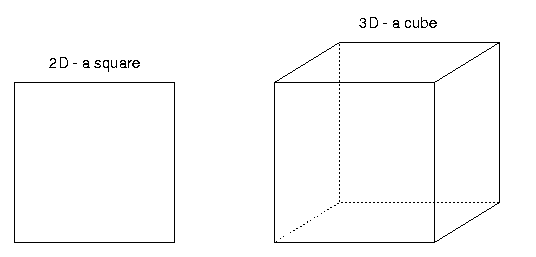
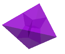
Triangulation of a d-simplex with (d+1) vertices and mesh cells.
The vertices argument contains a vector with all d+1 vertices of the simplex. They must be given in an order such that the vectors from the first vertex to each of the others form a right-handed system. And I am not happy about the discrimination involved here.
The meshes generated in two and three dimensions are

| tria | The Triangulation to create. It needs to be empty upon calling this function. |
| vertices | The dim+1 corners of the simplex. |
Triangulation<2,2>, Triangulation<3,3>.| void GridGenerator::subdivided_hyper_cube | ( | Triangulation< dim, spacedim > & | tria, |
| const unsigned int | repetitions, | ||
| const double | left = 0., |
||
| const double | right = 1. |
||
| ) |
Same as hyper_cube(), but with the difference that not only one cell is created but each coordinate direction is subdivided into repetitions cells. Thus, the number of cells filling the given volume is repetitionsdim.
If dim < spacedim, this will create a dim dimensional object in the first dim coordinate directions embedded into the spacedim dimensional space with the remaining entries set to zero. For example, a Triangulation<2,3> will be a square in the xy plane with z=0.
Definition at line 1139 of file grid_generator.cc.
| void GridGenerator::hyper_rectangle | ( | Triangulation< dim, spacedim > & | tria, |
| const Point< dim > & | p1, | ||
| const Point< dim > & | p2, | ||
| const bool | colorize = false |
||
| ) |
Create a coordinate-parallel brick from the two diagonally opposite corner points p1 and p2.
If the colorize flag is true, then the boundary_ids of the boundary faces are assigned, such that the lower one in x-direction is 0, the upper one is 1. The indicators for the surfaces in y-direction are 2 and 3, the ones for z are 4 and 5. This corresponds to the numbers of faces of the unit square of cube as laid out in the documentation of the GeometryInfo class; see also the glossary entry on colorization. Importantly, however, in 3d colorization does not set boundary_ids of edges, but only of faces, because each boundary edge is shared between two faces and it is not clear how the boundary id of an edge should be set in that case.
Additionally, if colorize is true, material ids are assigned to the cells according to the octant their center is in: being in the right half space for any coordinate direction xi adds 2i. For instance, a cell with center point (1,-1,1) yields a material id 5, assuming that the center of the hyper rectangle lies at the origin. No manifold id is set for the cells.
If dim < spacedim, this will create a dim dimensional object in the first dim coordinate directions embedded into the spacedim dimensional space with the remaining entries set to zero. For example, a Triangulation<2,3> will be a rectangle in the xy plane with z=0, defined by the two opposing corners p1 and p2.
Definition at line 356 of file grid_generator.cc.
| void GridGenerator::subdivided_hyper_rectangle | ( | Triangulation< dim, spacedim > & | tria, |
| const std::vector< unsigned int > & | repetitions, | ||
| const Point< dim > & | p1, | ||
| const Point< dim > & | p2, | ||
| const bool | colorize = false |
||
| ) |
Create a coordinate-parallel brick from the two diagonally opposite corner points p1 and p2. The number of cells in coordinate direction i is given by the integer repetitions[i].
To get cells with an aspect ratio different from that of the domain, use different numbers of subdivisions, given by repetitions, in different coordinate directions. The minimum number of subdivisions in each direction is 1.
If the colorize flag is true, then the boundary_ids of the surfaces are assigned, such that the lower one in x-direction is 0, the upper one is 1 (the left and the right vertical face). The indicators for the surfaces in y-direction are 2 and 3, the ones for z are 4 and 5. Additionally, material ids are assigned to the cells according to the octant their center is in: being in the right half plane for any coordinate direction xi adds 2i (see the glossary entry on colorization). For instance, the center point (1,-1,1) yields a material id 5 (this means that in 2d only material ids 0,1,2,3 are assigned independent from the number of repetitions).
Note that the colorize flag is ignored in 1d and is assumed to always be true. That means the boundary indicator is 0 on the left and 1 on the right. See step-15 for details.
If dim < spacedim, this will create a dim dimensional object in the first dim coordinate directions embedded into the spacedim dimensional space with the remaining entries set to zero. For example, a Triangulation<2,3> will be a rectangle in the xy plane with z=0, defined by the two opposing corners p1 and p2.
| tria | The Triangulation to create. It needs to be empty upon calling this function. |
| repetitions | A vector of dim positive values denoting the number of cells to generate in that direction. |
| p1 | First corner point. |
| p2 | Second corner opposite to p1. |
| colorize | Assign different boundary ids if set to true. The same comments apply as for the hyper_rectangle() function. |
Definition at line 1163 of file grid_generator.cc.
| void GridGenerator::subdivided_hyper_rectangle | ( | Triangulation< dim > & | tria, |
| const std::vector< std::vector< double >> & | step_sizes, | ||
| const Point< dim > & | p_1, | ||
| const Point< dim > & | p_2, | ||
| const bool | colorize = false |
||
| ) |
Like the previous function. However, here the second argument does not denote the number of subdivisions in each coordinate direction, but a sequence of step sizes for each coordinate direction. The domain will therefore be subdivided into step_sizes[i].size() cells in coordinate direction i, with width step_sizes[i][j] for the jth cell.
This function is therefore the right one to generate graded meshes where cells are concentrated in certain areas, rather than a uniformly subdivided mesh as the previous function generates.
The step sizes have to add up to the dimensions of the hyper rectangle specified by the points p1 and p2.
Definition at line 1314 of file grid_generator.cc.
| void GridGenerator::subdivided_hyper_rectangle | ( | Triangulation< dim > & | tria, |
| const std::vector< std::vector< double >> & | spacing, | ||
| const Point< dim > & | p, | ||
| const Table< dim, types::material_id > & | material_id, | ||
| const bool | colorize = false |
||
| ) |
Like the previous function, but with the following twist: the material_id argument is a dim-dimensional array that, for each cell, indicates which material_id should be set. In addition, and this is the major new functionality, if the material_id of a cell is (unsigned char)(-1), then that cell is deleted from the triangulation, i.e. the domain will have a void there.
| void GridGenerator::cheese | ( | Triangulation< dim, spacedim > & | tria, |
| const std::vector< unsigned int > & | holes | ||
| ) |
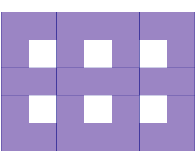
Rectangular domain with rectangular pattern of holes.
The domain itself is rectangular, very much as if it had been generated by subdivided_hyper_rectangle(). The argument holes specifies how many square holes the domain should have in each coordinate direction. The total number of mesh cells in that direction is then twice this number plus one.
The number of holes in one direction must be at least one.
An example with two by three holes is
If dim < spacedim, this will create a dim dimensional object in the first dim coordinate directions embedded into the spacedim dimensional space with the remaining entries set to zero.
| tria | The Triangulation to create. It needs to be empty upon calling this function. |
| holes | Positive number of holes in each of the dim directions. |
Definition at line 1796 of file grid_generator.cc.
| void GridGenerator::plate_with_a_hole | ( | Triangulation< dim > & | tria, |
| const double | inner_radius = 0.4, |
||
| const double | outer_radius = 1., |
||
| const double | pad_bottom = 2., |
||
| const double | pad_top = 2., |
||
| const double | pad_left = 1., |
||
| const double | pad_right = 1., |
||
| const Point< dim > | center = Point< dim >(), |
||
| const types::manifold_id | polar_manifold_id = 0, |
||
| const types::manifold_id | tfi_manifold_id = 1, |
||
| const double | L = 1., |
||
| const unsigned int | n_slices = 2, |
||
| const bool | colorize = false |
||
| ) |
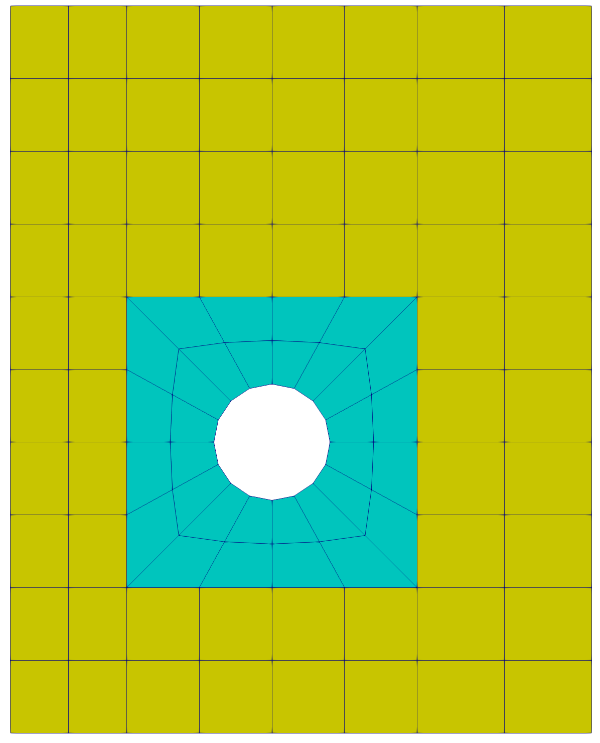
Rectangular plate with an (offset) cylindrical hole.
Generate a rectangular plate with an (offset) cylindrical hole. The geometry consists of 2 regions: The first is a square region with length outer_radius and a hole of radius inner_radius . Cells in this region will have TransfiniteInterpolationManifold with manifold id tfi_manifold_id attached to them. Additionally, the boundary faces of the hole will be associated with a PolarManifold (in 2D) or CylindricalManifold (in 3D). The center of this region can be prescribed via center , namely the axis of the hole will be located at center . The second region describes the remainder of the bulk material. It is specified via padding parameters pad_bottom, padding_top, padding_left and padding_right. All cells in this region will have a FlatManifold attached to them. The final width of the plate will be padding_left + 2*outer_radius + padding_right, while its length is padding_top + 2*outer_radius + padding_bottom. Three out of four paddings are allowed to be zero.
Here is the non-symmetric grid (after one global refinement, colored according to manifold id) in 2D:
and in 3D:
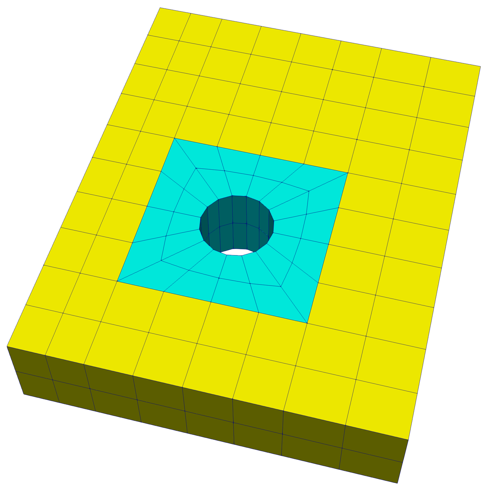
In 3D, triangulation will be extruded in the z-direction by the total height of L using n_slices slices (minimum is 2).
If the colorize flag is true, the boundary_ids of the boundary faces are assigned such that the lower one in the x-direction is 0, and the upper one is 1 (see the glossary entry on colorization). The indicators for the surfaces in the y-direction are 2 and 3, and the ones for the z-direction are 5 and 6. The hole boundary has indicator 4.
| void GridGenerator::general_cell | ( | Triangulation< dim > & | tria, |
| const std::vector< Point< dim >> & | vertices, | ||
| const bool | colorize = false |
||
| ) |
A general quadrilateral in 2d or a general hexahedron in 3d. It is the responsibility of the user to provide the vertices in the right order (see the documentation of the GeometryInfo class) because the vertices are stored in the same order as they are given. It is also important to make sure that the volume of the cell is positive.
If the argument colorize is false, then all boundary indicators are set to zero for 2d and 3d. If it is true, the boundary is colorized as in hyper_rectangle() (see the glossary entry on colorization). In 1d the indicators are always colorized, see hyper_rectangle().
Definition at line 775 of file grid_generator.cc.
| void GridGenerator::parallelogram | ( | Triangulation< dim > & | tria, |
| const Point< dim >(&) | corners[dim], | ||
| const bool | colorize = false |
||
| ) |
A parallelogram. The first corner point is the origin. The dim adjacent points are the ones given in the second argument and the fourth point will be the sum of these two vectors. Colorizing is done in the same way as in hyper_rectangle().
| void GridGenerator::parallelepiped | ( | Triangulation< dim > & | tria, |
| const Point< dim >(&) | corners[dim], | ||
| const bool | colorize = false |
||
| ) |
A parallelepiped. The first corner point is the origin. The dim adjacent points are vectors describing the edges of the parallelepiped with respect to the origin. Additional points are sums of these dim vectors. Colorizing is done according to hyper_rectangle().
GridReordering::reorder_grid). In other words, if reordering of the vertices does occur, the ordering of vertices in the array of corners will no longer refer to the same triangulation.Definition at line 835 of file grid_generator.cc.
| void GridGenerator::subdivided_parallelepiped | ( | Triangulation< dim > & | tria, |
| const unsigned int | n_subdivisions, | ||
| const Point< dim >(&) | corners[dim], | ||
| const bool | colorize = false |
||
| ) |
A subdivided parallelepiped. The first corner point is the origin. The dim adjacent points are vectors describing the edges of the parallelepiped with respect to the origin. Additional points are sums of these dim vectors. The variable n_subdivisions designates the number of subdivisions in each of the dim directions. Colorizing is done according to hyper_rectangle().
Definition at line 849 of file grid_generator.cc.
| void GridGenerator::subdivided_parallelepiped | ( | Triangulation< dim > & | tria, |
| const unsigned int(&) | n_subdivisions[dim], | ||
| const Point< dim >(&) | corners[dim], | ||
| const bool | colorize = false |
||
| ) |
A subdivided parallelepiped, i.e., the same as above, but where the number of subdivisions in each of the dim directions may vary. Colorizing is done according to hyper_rectangle().
Definition at line 866 of file grid_generator.cc.
| void GridGenerator::subdivided_parallelepiped | ( | Triangulation< dim, spacedim > & | tria, |
| const Point< spacedim > & | origin, | ||
| const std::array< Tensor< 1, spacedim >, dim > & | edges, | ||
| const std::vector< unsigned int > & | subdivisions = std::vector<unsigned int>(), |
||
| const bool | colorize = false |
||
| ) |
A subdivided parallelepiped.
| tria | The Triangulation to create. It needs to be empty upon calling this function. |
| origin | First corner of the parallelepiped. |
| edges | An array of dim tensors describing the length and direction of the edges from origin. |
| subdivisions | Number of subdivisions in each of the dim directions. Each entry must be positive. An empty vector is equivalent to one subdivision in each direction. |
| colorize | Assign different boundary ids if set to true (see the glossary entry on colorization). |
dim and spacedim.Definition at line 898 of file grid_generator.cc.
| void GridGenerator::enclosed_hyper_cube | ( | Triangulation< dim > & | tria, |
| const double | left = 0., |
||
| const double | right = 1., |
||
| const double | thickness = 1., |
||
| const bool | colorize = false |
||
| ) |
Hypercube with a layer of hypercubes around it. The first two parameters give the lower and upper bound of the inner hypercube in all coordinate directions. thickness marks the size of the layer cells.
If the flag colorize is set, the outer cells get material ids according to the following scheme: extending over the inner cube in (+/-) x-direction: 1/2. In y-direction 4/8, in z-direction 16/32. The cells at corners and edges (3d) get these values bitwise or'd (see also the glossary entry on colorization).
Presently only available in 2d and 3d.
| void GridGenerator::hyper_ball | ( | Triangulation< dim > & | tria, |
| const Point< dim > & | center = Point< dim >(), |
||
| const double | radius = 1., |
||
| const bool | attach_spherical_manifold_on_boundary_cells = false |
||
| ) |
Initialize the given triangulation with several coarse mesh cells that cover a hyperball, i.e. a circle or a ball around center with given radius.
In order to avoid degenerate cells at the boundaries, the circle is triangulated by five cells, the ball by seven cells. Specifically, these cells are one cell in the center plus one "cap" cell on each of the faces of this center cell. This ensures that under repeated refinement, none of the cells at the outer boundary will degenerate to have an interior angle approaching 180 degrees. The diameter of the center cell is chosen so that the aspect ratio of the boundary cells after one refinement is optimized.
This function is declared to exist for triangulations of all space dimensions, but throws an error if called in 1d.
By default, the manifold_id is set to 0 on the boundary faces, 1 on the the boundary cells, and types::flat_manifold_id on the central cell and on internal faces.
A SphericalManifold is attached by default to the boundary faces for correct placement of boundary vertices upon refinement and to be able to use higher order mappings. However, it turns out that this strategy may not be the optimal one to create a good a mesh for a hyperball. The "Possibilities for extensions" section of step-6 has an extensive discussion of how one would construct better meshes and what one needs to do for it. Selecting the argument attach_spherical_manifold_on_boundary_cells to true attaches a SphericalManifold manifold also to the boundary cells, and not only to the boundary faces.
| void GridGenerator::hyper_sphere | ( | Triangulation< spacedim-1, spacedim > & | tria, |
| const Point< spacedim > & | center = Point<spacedim>(), |
||
| const double | radius = 1. |
||
| ) |
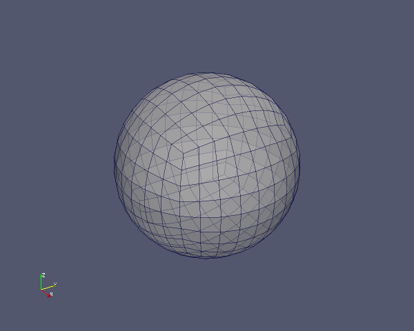
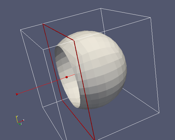
Creates a hyper sphere, i.e., a surface of a ball in spacedim dimensions. This function only exists for dim+1=spacedim in 2 and 3 space dimensions. (To create a mesh of a ball, use GridGenerator::hyper_ball().)
By default, all manifold ids of the triangulation are set to zero, and a SphericalManifold is attached to the grid.
The following pictures are generated with:
See the documentation module on manifolds for more details.
Definition at line 3417 of file grid_generator.cc.
| void GridGenerator::quarter_hyper_ball | ( | Triangulation< dim > & | tria, |
| const Point< dim > & | center = Point< dim >(), |
||
| const double | radius = 1. |
||
| ) |
This class produces a hyper-ball intersected with the positive orthant relative to center, which contains three elements in 2d and four in 3d.
The boundary indicators for the final triangulation are 0 for the curved boundary and 1 for the cut plane. The manifold id for the curved boundary is set to zero, and a SphericalManifold is attached to it.
| void GridGenerator::half_hyper_ball | ( | Triangulation< dim > & | tria, |
| const Point< dim > & | center = Point< dim >(), |
||
| const double | radius = 1. |
||
| ) |
This class produces a half hyper-ball around center, which contains four elements in 2d and 6 in 3d. The cut plane is perpendicular to the x-axis.
The boundary indicators for the final triangulation are 0 for the curved boundary and 1 for the cut plane. The manifold id for the curved boundary is set to zero, and a SphericalManifold is attached to it.
| void GridGenerator::cylinder | ( | Triangulation< dim > & | tria, |
| const double | radius = 1., |
||
| const double | half_length = 1. |
||
| ) |
Create a cylinder around the \(x\)-axis. The cylinder extends from x=-half_length to x=+half_length and its projection into the yz-plane is a circle of radius radius.
In two dimensions, the cylinder is a rectangle from x=-half_length to x=+half_length and from y=-radius to y=radius.
The boundaries are colored according to the following scheme: 0 for the hull of the cylinder, 1 for the left hand face and 2 for the right hand face (see the glossary entry on colorization).
If you want the cylinder to revolve around a different axis than the \(x\)-axis, then simply rotate the mesh generated by this function using the GridTools::transform() function using a rotation operator as argument.
The manifold id for the hull of the cylinder is set to zero, and a CylindricalManifold is attached to it.
| void GridGenerator::truncated_cone | ( | Triangulation< dim > & | tria, |
| const double | radius_0 = 1.0, |
||
| const double | radius_1 = 0.5, |
||
| const double | half_length = 1.0 |
||
| ) |
Create a cut cone around the x-axis. The cone extends from x=-half_length to x=half_length and its projection into the yz-plane is a circle of radius radius_0 at x=-half_length and a circle of radius radius_1 at x=+half_length. In between the radius is linearly decreasing.
In two dimensions, the cone is a trapezoid from x=-half_length to x=+half_length and from y=-radius_0 to y=radius_0 at x=-half_length and from y=-radius_1 to y=radius_1 at x=+half_length. In between the range of y is linearly decreasing.
The boundaries are colored according to the following scheme: 0 for the hull of the cone, 1 for the left hand face, and 2 for the right hand face (see the glossary entry on colorization). Both the boundary indicators and the manifold indicators are set.
In three dimensions, the manifold id of the hull is set to zero, and a CylindricalManifold is attached to it.
| void GridGenerator::hyper_cross | ( | Triangulation< dim, spacedim > & | tria, |
| const std::vector< unsigned int > & | sizes, | ||
| const bool | colorize_cells = false |
||
| ) |
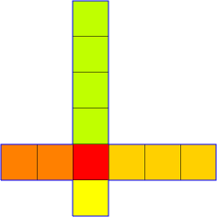
A center cell with stacks of cell protruding from each surface.
Each of the square mesh cells is Cartesian and has size one in each coordinate direction. The center of cell number zero is the origin.
| tria | A Triangulation object which has to be empty. |
| sizes | A vector of integers of dimension GeometryInfo<dim>::faces_per_cell with the following meaning: the legs of the cross are stacked on the faces of the center cell, in the usual order of deal.II cells, namely first \(-x\), then \(x\), then \(-y\) and so on. The corresponding entries in sizes name the number of cells stacked on this face. All numbers may be zero, thus L- and T-shaped domains are specializations of this domain. |
| colorize_cells | If colorization is enabled, then the material id of a cells corresponds to the leg it is in. The id of the center cell is zero, and then the legs are numbered starting at one (see the glossary entry on colorization). |
Examples in two and three dimensions are
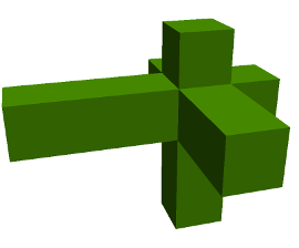
Definition at line 2264 of file grid_generator.cc.
| void GridGenerator::hyper_L | ( | Triangulation< dim > & | tria, |
| const double | left = -1., |
||
| const double | right = 1., |
||
| const bool | colorize = false |
||
| ) |
Initialize the given triangulation with a hyper-L (in 2d or 3d) consisting of exactly 2^dim-1 cells. It produces the hypercube with the interval [left,right] without the hypercube made out of the interval [(left+right)/2,right] for each coordinate. Because the domain is about the simplest one with a reentrant (i.e., non-convex) corner, solutions of many partial differential equation have singularities at this corner. That is, at the corner, the gradient or a higher derivative (depending on the boundary conditions chosen) does not remain bounded. As a consequence, this domain is often used to test convergence of schemes when the solution lacks regularity.
If the colorize flag is true, the boundary_ids of the surfaces are assigned such that the left boundary is 0 and the others are assigned counterclockwise in ascending order (see the glossary entry on colorization). The colorize option only works in two dimensions.
This function will create the classical L-shape in 2d and it will look like the following in 3d:
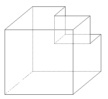
This function exists for triangulations of all space dimensions, but throws an error if called in 1d.
| void GridGenerator::hyper_cube_slit | ( | Triangulation< dim > & | tria, |
| const double | left = 0., |
||
| const double | right = 1., |
||
| const bool | colorize = false |
||
| ) |
Initialize the given Triangulation with a hypercube with a slit. In each coordinate direction, the hypercube extends from left to right.
In 2d, the split goes in vertical direction from x=(left+right)/2, y=left to the center of the square at x=y=(left+right)/2.
In 3d, the 2d domain is just extended in the z-direction, such that a plane cuts the lower half of a rectangle in two. This function is declared to exist for triangulations of all space dimensions, but throws an error if called in 1d.
If colorize is set to true, the faces forming the slit are marked with boundary id 1 and 2, respectively (see the glossary entry on colorization).
| void GridGenerator::hyper_shell | ( | Triangulation< dim > & | tria, |
| const Point< dim > & | center, | ||
| const double | inner_radius, | ||
| const double | outer_radius, | ||
| const unsigned int | n_cells = 0, |
||
| bool | colorize = false |
||
| ) |
Produce a hyper-shell, the region between two spheres around center, with given inner_radius and outer_radius. The number n_cells indicates the number of cells of the resulting triangulation, i.e., how many cells form the ring (in 2d) or the shell (in 3d).
If the flag colorize is true, then the outer boundary will have the indicator 1 while the inner boundary has id zero. In 3d, this applies to both the faces and the edges of these boundaries. If the flag is false, both have indicator zero (see the glossary entry on colorization).
All manifold ids are set to zero, and a SphericalManifold is attached to every cell and face of the triangulation.
In 2d, the number n_cells of elements for this initial triangulation can be chosen arbitrarily. If the number of initial cells is zero (as is the default), then it is computed adaptively such that the resulting elements have the least aspect ratio.
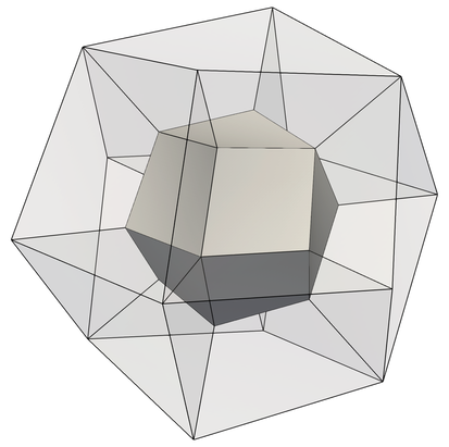
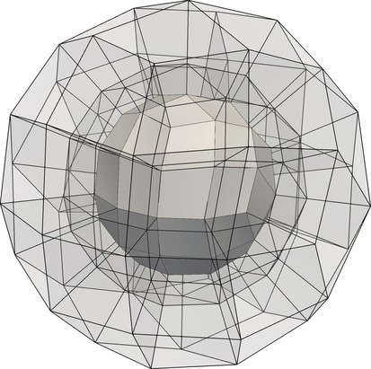
In 3d, only certain numbers are allowed, 6 (or the default 0) for a surface based on a hexahedron (i.e. 6 panels on the inner sphere extruded in radial direction to form 6 cells), 12 for the rhombic dodecahedron, and 96. This choice dates from an older version of deal.II before the Manifold classes were implemented: today all three choices are roughly equivalent (after performing global refinement, of course).
The grids with 12 and 96 cells are plotted below:
| void GridGenerator::half_hyper_shell | ( | Triangulation< dim > & | tria, |
| const Point< dim > & | center, | ||
| const double | inner_radius, | ||
| const double | outer_radius, | ||
| const unsigned int | n_cells = 0, |
||
| const bool | colorize = false |
||
| ) |
Produce a half hyper-shell, i.e. the space between two circles in two space dimensions and the region between two spheres in 3d, with given inner and outer radius and a given number of elements for this initial triangulation. However, opposed to the previous function, it does not produce a whole shell, but only one half of it, namely that part for which the first component is restricted to non-negative values. The purpose of this class is to enable computations for solutions which have rotational symmetry, in which case the half shell in 2d represents a shell in 3d.
If the number of initial cells is zero (as is the default), then it is computed adaptively such that the resulting elements have the least aspect ratio.
If colorize is set to true, the inner, outer, and the part of the boundary where \(x=0\), get indicator 0, 1, and 2, respectively. Otherwise all indicators are set to 0 (see the glossary entry on colorization).
All manifold ids are set to zero, and a SphericalManifold is attached to the triangulation.
| void GridGenerator::quarter_hyper_shell | ( | Triangulation< dim > & | tria, |
| const Point< dim > & | center, | ||
| const double | inner_radius, | ||
| const double | outer_radius, | ||
| const unsigned int | n_cells = 0, |
||
| const bool | colorize = false |
||
| ) |
Produce a domain that is the intersection between a hyper-shell with given inner and outer radius, i.e. the space between two circles in two space dimensions and the region between two spheres in 3d, and the positive quadrant (in 2d) or octant (in 3d). In 2d, this is indeed a quarter of the full annulus, while the function is a misnomer in 3d because there the domain is not a quarter but one eighth of the full shell.
If the number of initial cells is zero (as is the default), then it is computed adaptively such that the resulting elements have the least aspect ratio in 2d.
If colorize is set to true, the inner, outer, left, and right boundary get indicator 0, 1, 2, and 3 in 2d, respectively. Otherwise all indicators are set to 0. In 3d indicator 2 is at the face \(x=0\), 3 at \(y=0\), 4 at \(z=0\) (see the glossary entry on colorization).
All manifold ids are set to zero, and a SphericalManifold is attached to the triangulation.
| void GridGenerator::cylinder_shell | ( | Triangulation< dim > & | tria, |
| const double | length, | ||
| const double | inner_radius, | ||
| const double | outer_radius, | ||
| const unsigned int | n_radial_cells = 0, |
||
| const unsigned int | n_axial_cells = 0 |
||
| ) |
Produce a domain that is the space between two cylinders in 3d, with given length, inner and outer radius and a given number of elements. The cylinder shell is built around the \(z\)-axis with the two faces located at \(z = 0\) and \(z = \) length.
If n_radial_cells is zero (as is the default), then it is computed adaptively such that the resulting elements have the least aspect ratio. The same holds for n_axial_cells.
All manifold ids are set to zero, and a CylindricalManifold is attached to the triangulation.
| void GridGenerator::torus | ( | Triangulation< dim, spacedim > & | tria, |
| const double | R, | ||
| const double | r | ||
| ) |
Produce the volume or surface mesh of a torus. The axis of the torus is the \(y\)-axis while the plane of the torus is the \(x\)- \(z\) plane.
If dim is 3, the mesh will be the volume of the torus and this function attaches a TorusManifold to all boundary cells and faces (which are marked with a manifold id of 0).
If dim is 2, the mesh will describe the surface of the torus and this function attaches a TorusManifold to all cells and faces (which are marked with a manifold id of 0).
| tria | The triangulation to be filled. |
| R | The radius of the circle, which forms the middle line of the torus containing the loop of cells. Must be greater than r. |
| r | The inner radius of the torus. |
| void GridGenerator::hyper_cube_with_cylindrical_hole | ( | Triangulation< dim > & | triangulation, |
| const double | inner_radius = .25, |
||
| const double | outer_radius = .5, |
||
| const double | L = .5, |
||
| const unsigned int | repetitions = 1, |
||
| const bool | colorize = false |
||
| ) |
This class produces a square in the xy-plane with a cylindrical hole in the middle. The square and the circle are centered at the origin. In 3d, this geometry is extruded in \(z\) direction to the interval \([0,L]\).
The inner boundary has a manifold id of \(0\) and a boundary id of \(6\). This function attaches a PolarManifold or CylindricalManifold to the interior boundary in 2d and 3d respectively. The other faces have boundary ids of \(0, 1, 2, 3, 4\), or \(5\) given in the standard order of faces in 2d or 3d.
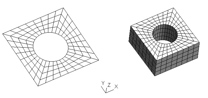
It is implemented in 2d and 3d, and takes the following arguments:
| triangulation | The triangulation to be filled. |
| inner_radius | Radius of the internal hole. |
| outer_radius | Half of the edge length of the square. |
| L | Extension in z-direction (only used in 3d). |
| repetitions | Number of subdivisions along the z-direction. |
| colorize | Whether to assign different boundary indicators to different faces (see the glossary entry on colorization). The colors are given in lexicographic ordering for the flat faces (0 to 3 in 2d, 0 to 5 in 3d) plus the curved hole (4 in 2d, and 6 in 3d). If colorize is set to false, then flat faces get the number 0 and the hole gets number 1. |
| void GridGenerator::concentric_hyper_shells | ( | Triangulation< dim > & | triangulation, |
| const Point< dim > & | center, | ||
| const double | inner_radius = 0.125, |
||
| const double | outer_radius = 0.25, |
||
| const unsigned int | n_shells = 1, |
||
| const double | skewness = 0.1, |
||
| const unsigned int | n_cells_per_shell = 0, |
||
| const bool | colorize = false |
||
| ) |
Produce a grid consisting of concentric shells. The primary difference between this function and GridGenerator::hyper_shell is that this function permits unevenly spaced (in the radial direction) coarse level cells.
The parameters center, inner_radius, and outer_radius behave in the same way as the first three arguments to GridGenerator::hyper_shell. n_shells gives the total number of shells to use (i.e., the number of cells in the radial direction). The outer radius of the \(k\)th shell is given by
\[ r = r_{\text{inner}} + (r_\text{outer} - r_\text{inner}) \frac{1 - \tanh(\text{skewness}(1 - k/\text{n_shells}))} {\tanh(\text{skewness})} \]
where skewness is a parameter controlling the shell spacing in the radial direction: values of skewness close to zero correspond to even spacing, while larger values of skewness (such as \(2\) or \(3\)) correspond to shells biased to the inner radius.
n_cells_per_shell is the same as in GridGenerator::hyper_shell: in 2d the default choice of zero will result in 8 cells per shell (and 12 in 3d). The only valid values in 3d are 6 (the default), 12, and 96 cells: see the documentation of GridGenerator::hyper_shell for more information.
If colorize is true then the outer boundary of the merged shells has a boundary id of \(1\) and the inner boundary has a boundary id of \(0\).
Example: The following code (see, e.g., step-10 for instructions on how to visualize GNUPLOT output)
generates the following output:

Definition at line 4738 of file grid_generator.cc.
| void GridGenerator::moebius | ( | Triangulation< 3, 3 > & | tria, |
| const unsigned int | n_cells, | ||
| const unsigned int | n_rotations, | ||
| const double | R, | ||
| const double | r | ||
| ) |
Produce a ring of cells in 3d that is cut open, twisted and glued together again. This results in a kind of moebius-loop.
| tria | The triangulation to be worked on. |
| n_cells | The number of cells in the loop. Must be greater than 4. |
| n_rotations | The number of rotations (Pi/2 each) to be performed before gluing the loop together. |
| R | The radius of the circle, which forms the middle line of the torus containing the loop of cells. Must be greater than r. |
| r | The radius of the cylinder bent together as a loop. |
| void GridGenerator::merge_triangulations | ( | const Triangulation< dim, spacedim > & | triangulation_1, |
| const Triangulation< dim, spacedim > & | triangulation_2, | ||
| Triangulation< dim, spacedim > & | result, | ||
| const double | duplicated_vertex_tolerance = 1.0e-12, |
||
| const bool | copy_manifold_ids = false |
||
| ) |
Given the two triangulations specified as the first two arguments, create the triangulation that contains the cells of both triangulation and store it in the third parameter. Previous content of result will be deleted.
This function is most often used to compose meshes for more complicated geometries if the geometry can be composed of simpler parts for which functions exist to generate coarse meshes. For example, the channel mesh used in step-35 could in principle be created using a mesh created by the GridGenerator::hyper_cube_with_cylindrical_hole function and several rectangles, and merging them using the current function. The rectangles will have to be translated to the right for this, a task that can be done using the GridTools::shift function (other tools to transform individual mesh building blocks are GridTools::transform, GridTools::rotate, and GridTools::scale).
Vertices that are less than duplicated_vertex_tolerance apart will be merged together. It is usually necessary to set this value to something that depends on the input triangulations in some way. One reasonable choice is to use the minimum distance between all adjacent vertices of the input mesh divided by some constant:
This will merge any vertices that are closer than any pair of vertices on the input meshes.
copy_manifold_ids is set to true, manifold ids will be copied. Boundary indicators are never copied. In other words, if the two coarse meshes have anything but the default boundary indicators, then you will have to set boundary indicators again by hand in the output triangulation.result, nor does it set any manifold ids.Definition at line 4325 of file grid_generator.cc.
| void GridGenerator::merge_triangulations | ( | const std::initializer_list< const Triangulation< dim, spacedim > *const > | triangulations, |
| Triangulation< dim, spacedim > & | result, | ||
| const double | duplicated_vertex_tolerance = 1.0e-12, |
||
| const bool | copy_manifold_ids = false |
||
| ) |
Same as above but allows to merge more than two triangulations at once. The following gives an example of how to use this function:
Definition at line 4142 of file grid_generator.cc.
| void GridGenerator::create_union_triangulation | ( | const Triangulation< dim, spacedim > & | triangulation_1, |
| const Triangulation< dim, spacedim > & | triangulation_2, | ||
| Triangulation< dim, spacedim > & | result | ||
| ) |
Given the two triangulations specified as the first two arguments, create the triangulation that contains the finest cells of both triangulation and store it in the third parameter. Previous content of result will be deleted.
triangulation_1 and triangulation_2 have the same manifold descriptions. The output Triangulation has the same manifold ids as these two triangulations.Definition at line 4352 of file grid_generator.cc.
| void GridGenerator::create_triangulation_with_removed_cells | ( | const Triangulation< dim, spacedim > & | input_triangulation, |
| const std::set< typename Triangulation< dim, spacedim >::active_cell_iterator > & | cells_to_remove, | ||
| Triangulation< dim, spacedim > & | result | ||
| ) |
This function creates a triangulation that consists of the same cells as are present in the first argument, except those cells that are listed in the second argument. The purpose of the function is to generate geometries subtractively from the geometry described by an existing triangulation. A prototypical case is a 2d domain with rectangular holes. This can be achieved by first meshing the entire domain and then using this function to get rid of the cells that are located at the holes. Likewise, you could create the mesh that GridGenerator::hyper_L() produces by starting with a GridGenerator::hyper_cube(), refining it once, and then calling the current function with a single cell in the second argument.
| [in] | input_triangulation | The original triangulation that serves as the template from which the new one is to be created. |
| [in] | cells_to_remove | A list of cells of the triangulation provided as first argument that should be removed (i.e., that should not show up in the result. |
| [out] | result | The resulting triangulation that consists of the same cells as are in input_triangulation, with the exception of the cells listed in cells_to_remove. |
result, nor does it set any manifold ids.Definition at line 4413 of file grid_generator.cc.
| void GridGenerator::extrude_triangulation | ( | const Triangulation< 2, 2 > & | input, |
| const unsigned int | n_slices, | ||
| const double | height, | ||
| Triangulation< 3, 3 > & | result | ||
| ) |
Take a 2d Triangulation that is being extruded in z direction by the total height of height using n_slices slices (minimum is 2). The boundary indicators of the faces of input are going to be assigned to the corresponding side walls in z direction. The bottom and top get the next two free boundary indicators.
input must be a coarse mesh that has no refined cells.input and output have different spatial dimensions no manifold objects are copied (nor are any manifold ids set) by this function. Definition at line 4465 of file grid_generator.cc.
| void GridGenerator::extrude_triangulation | ( | const Triangulation< 2, 2 > & | input, |
| const std::vector< double > & | slice_coordinates, | ||
| Triangulation< 3, 3 > & | result | ||
| ) |
Overload of the previous function. Take a 2d Triangulation that is being extruded. Differing from the previous function taking height and number of slices for uniform extrusion, this function takes z-axis values slice_coordinates where the slicing will happen. The boundary indicators of the faces of input are going to be assigned to the corresponding side walls in z direction. The bottom and top get the next two free boundary indicators.
input must be a coarse mesh that has no refined cells.input and output have different spatial dimensions no manifold objects are copied (nor are any manifold ids set) by this function.Definition at line 4490 of file grid_generator.cc.
| void GridGenerator::flatten_triangulation | ( | const Triangulation< dim, spacedim1 > & | in_tria, |
| Triangulation< dim, spacedim2 > & | out_tria | ||
| ) |
Given an input triangulation in_tria, this function makes a new flat triangulation out_tria which contains a single level with all active cells of the input triangulation. If spacedim1 and spacedim2 are different, only the smallest spacedim components of the vertices are copied over. This is useful to create a Triangulation<2,3> out of a Triangulation<2,2>, or to project a Triangulation<2,3> into a Triangulation<2,2>, by neglecting the z components of the vertices.
No internal checks are performed on the vertices, which are assumed to make sense topologically in the target spacedim2 dimensional space. If this is not the case, you will encounter problems when using the triangulation later on.
All information about cell manifold_ids and material ids are copied from one triangulation to the other, and only the boundary manifold_ids and boundary_ids are copied over from the faces of in_tria to the faces of out_tria. If you need to specify manifold ids on interior faces, they have to be specified manually after the triangulation is created.
This function will fail if the input Triangulation is of type parallel::distributed::Triangulation, as well as when the input Triangulation contains hanging nodes.
input and output have different spatial dimensions no manifold objects are copied by this function: you must attach new manifold objects to out_tria.Definition at line 4979 of file grid_generator.cc.
| std::map< typename MeshType< dim-1, spacedim >::cell_iterator, typename MeshType< dim, spacedim >::face_iterator > GridGenerator::extract_boundary_mesh | ( | const MeshType< dim, spacedim > & | volume_mesh, |
| MeshType< dim-1, spacedim > & | surface_mesh, | ||
| const std::set< types::boundary_id > & | boundary_ids = std::set<types::boundary_id>() |
||
| ) |
This function implements a boundary subgrid extraction. Given a <dim,spacedim>-Triangulation (the "volume mesh") the function extracts a subset of its boundary (the "surface mesh"). The boundary to be extracted is specified by a list of boundary_ids. If none is specified the whole boundary will be extracted. The function is used in step-38.
The function also builds a mapping linking the cells on the surface mesh to the corresponding faces on the volume one. This mapping is the return value of the function.
| MeshType | A type that satisfies the requirements of the MeshType concept. The map that is returned will be between cell iterators pointing into the container describing the surface mesh and face iterators of the volume mesh container. If MeshType is DoFHandler or hp::DoFHandler, then the function will re-build the triangulation underlying the second argument and return a map between appropriate iterators into the MeshType arguments. However, the function will not actually distribute degrees of freedom on this newly created surface mesh. |
| dim | The dimension of the cells of the volume mesh. For example, if dim==2, then the cells are quadrilaterals that either live in the plane, or form a surface in a higher-dimensional space. The dimension of the cells of the surface mesh is consequently dim-1. |
| spacedim | The dimension of the space in which both the volume and the surface mesh live. |
| [in] | volume_mesh | A container of cells that define the volume mesh. |
| [out] | surface_mesh | A container whose associated triangulation will be built to consist of the cells that correspond to the (selected portion of) the boundary of the volume mesh. |
| [in] | boundary_ids | A list of boundary indicators denoting that subset of faces of volume cells for which this function should extract the surface mesh. If left at its default, i.e., if the set is empty, then the function operates on all boundary faces. |
volume_mesh and surface_mesh have different spatial dimensions no manifold objects are copied by this function: you must attach new manifold objects to surface_mesh. Definition at line 5083 of file grid_generator.cc.
 1.8.11

